Services
Services
Project description
AERODYNAMIC DESIGN
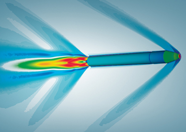
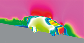
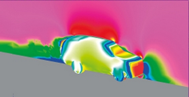
Aerodynamic performance analysis for:
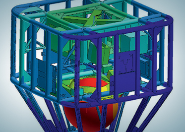
Aerodynamic performance analysis for space launch systems (SLS) structures and infrastructure affected by wind loads:
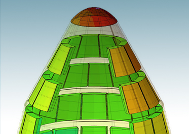
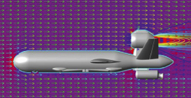
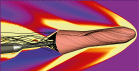
Analysis and optimization of aerodynamic performance for various products:
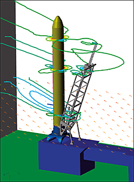
Aerodynamic performance analysis for:
Aerodynamic performance analysis for space launch systems (SLS) structures and infrastructure affected by wind loads:
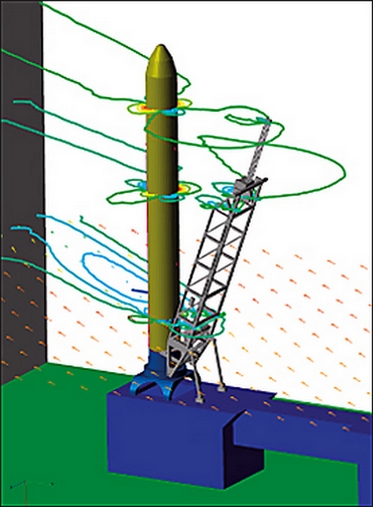
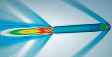
Analysis and optimization of aerodynamic performance for various products:
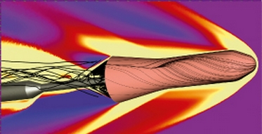
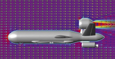


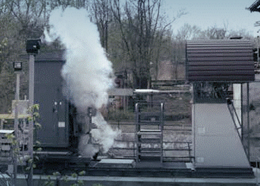
Ground experiments to determine the aerodynamic performance of aircraft at supersonic and hypersonic flight speeds are performed in an impulse wind tunnel at Yuzhnoye State Design Office..
The impulse wind tunnel (IWT) supports weighing, vent, and optical tests of scaled aircraft models and can simulate quasi-full-scale aircraft flight conditions.
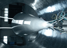
Force balance measurements
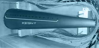
Drain tests
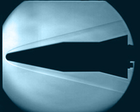
Optical tests
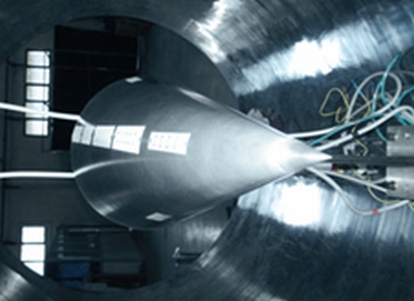
Force balance measurements
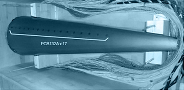
Drain tests
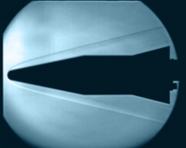
Optical tests
The IWT makes it possible to analyze experimental aerodynamic performance of the aircraft in the range of 1.5 to 7 Mach and angles of attack from – 7 to + 24 degrees..
Using a vacuum chamber in the IWT expands its operational range to 8 – 10 Mach.
The IWT uses an original in-model aerodynamic six-component strain-gauge balance and a high-speed measurement system, which enables highly accurate determination of the aerodynamic performance of the aircraft test scale models and measures displacements, velocities, and accelerations of their centers of mass along the X, Y, Z-axes.
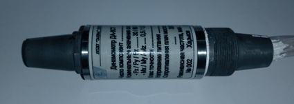
Six-component strain-gauge
aerodynamic balance
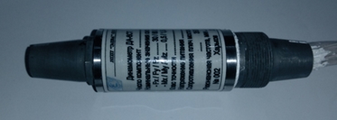
Six-component strain-gauge
aerodynamic balance
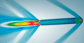
The HB-2 international reference model was used to test the IWT velocity modes..
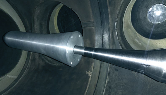
HB-2 reference model,
in the pulsed wind tunnel
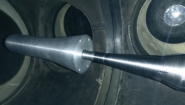
HB-2 reference model,
in the pulsed wind tunnel
The IWT is a short-term (impulse) wind tunnel characterized by lower consumption of energy (compressed air and electric power) as compared to continuous and periodic wind tunnels.
Using the IWT in an aerodynamic experiment significantly reduces the time and cost of aircraft development in the conceptual, preliminary, and detailed design phases.
| Mach | 1.5; 2; 3; 4; 5; 6; 7 |
| Working fluid initial pressure, atm | up to 200 |
| Working fluid | high-pressure air |
| Working fluid initial temperature, K | до 750 |
| Heater power, kW | 4х25 |
| Heater voltage, V | 380 |
| Nozzle exit diameter, m | 0,3 |
| Test section diameter, m | 0,505 |
| Run mode duration, s | from 0,2 до 0,8 |
https://autocaravanasgayo.com/servicios/
https://www.internacionaldvdspain.com/articles/decoracion/
https://exin.se/flytt-och-transport/
https://exin.se/flytt-och-transport/
https://exin.se/produkt/skap-kinnarps/
https://atharveducation.com/bds.php/
https://odin.rvbar.ru/poster/vorovayki/
https://newnoardicwave.com/privacy-policy/
https://einkaufsgemeinschaft.agritec.at/aktionen/
https://alejandrodavidovich.com/
https://mycreativitymypower.eu/
https://tunaskaryajakarta.sch.id/
